HP Latex 315 Printer Repair, 315 Printer Maintenance Service Error Code Repairs, Latex 315 Repair Los Angeles, Orange County and Riverside County!
Latex 315 printer repair Southern California!
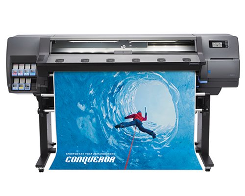
HP Latex 300 series Latex 315 printer repair and onsite service in Los Angeles and Orange County with broken belt, image defects, error messages, error codes and maintenance errors. We provide fast onsite HP Latex 315 printer maintenance service in Southern California. Our technicians have the knowledge and technical ability to repair latex 315 printer on the first visit.
We offer 6 months warranty on all Latex 315 replacement parts in Southern California. We carry most common parts to fix Latex 315 hardware failures with numerical error code on the first visit. We offer latex printer 315 printer service with broken belts and service error messages. We replace Latex 315 ink tubing system and purge the ink tubing system. We offer same-day on-site latex 315 54 and 64 inch belt kit replacement and lubricating the rails and run alignment test.
We specialize on repairing Latex 315 printers with maintenance kit 1, M-kit 2 and maintenance kit 3 replacement in Southern California.
We offer Latex 315 printer belt kit, carriage assembly, encoder strip, encoder sensor, main, ink supply station, (ISS) hard drive, Power supply, print heads, Rolling pump assembly, aerosol fan, and ink tubing system. Latex 315 / 335 / 365 yearly service contract includes 3 free visits to clean and inspect the latex printer. If your latex 315 printer fails during the 1 year service contract you only pay for parts and the labor is covered.
HP 315 Latex Inks and Print Heads
Take advantage of the versatile, durable performance of HP Latex Inks:• Scratch resistance comparable to hard-solvent inks on SAV and PVC banner— you can consider un-laminated use for short-term signage9• Prints are completely cured and dry inside the printer, and ready for immediate finishing and delivery• Six HP print heads provide 12,672 nozzles for robust and reliable quality print to print.
HP Latex Optimizer Achieve high image quality at high productivity:• Interacts with HP Latex Inks to rapidly immobilize pigments on the surface of the print.
High-efficiency curing High-speed printing with less energy and at lower temperatures:10• 17 m2/hr (183 ft2/hr) indoor quality, 31 m2/hr (334 ft2/hr)high-speed outdoor
Color consistency
Print panels or tiles with excellent color consistency for an edge-to-edge match:• i1 embedded spectra photometer enables automatic calibration12• Delivers consistent colors to <= 2 dE200013quality, 91 m2/hr. (980 ft2/hr.) maximum print speed.
Latex 315 Printer System Error Codes
Front-panel error codes for Latex 315 printers.
Under certain circumstances, a numeric error code appears on the front panel. Follow the advice in the Recommendation column to resolve the error. If the recommendation does not seem to solve the problem, call your service representative. If an error code appears on the front panel that is not included in this list, turn off the printer and then turn it back on. If the problem persists, call your service representative.
03.21:01 PSU under voltage detected.
- Turn off the printer and unplug both power cords.
2 .Check that the power cords are not visibly damaged.
3. Ensure that the input voltage is within specifications (180–264 V AC).
4. Plug in both power cords and make sure they are fully inserted.
5. Turn on the printer.
14.72:01 Zero voltage detected.
- Turn off the printer and unplug both power cords.
2. Check that the power cords are not visibly damaged.
3. Ensure that the input voltage is within specifications (180–264 V AC).
4. Plug in both power cords and make sure they are fully inserted.
5. Turn on the printer.
14.73:01 Very low voltage detected.
- Turn off the printer and unplug both power cords.
2. Check that the power cords are not visibly damaged.
3. Ensure that the input voltage is within specifications (180–264 V AC).
4. Plug in both power cords and make sure they are fully inserted
5. Turn on the printer.
14.74:01 Low voltage detected.
- Turn off the printer and unplug both power cords.
2. Check that the power cords are not visibly damaged
3.Ensure that the input voltage is within specifications (180–264 V AC).
4. Plug in both power cords and make sure they are fully inserted
5.Turn on the printer.
14.75:01 Excessive voltage detected.
- Turn off the printer and unplug both power cords.
2. Check that the power cords are not visibly damaged.
3. Ensure that the input voltage is within specifications (180–264 V AC).
4. Plug in both power cords and make sure they are fully inserted.
5. Turn on the printer.
14.87:10 Curing power regulator over temperature detected.
- Turn off the printer.
2. Check that the ambient temperature is within printer specifications (15–35°C).
3. Check that the electronic enclosures at the rear of the printer are properly ventilated.
4. Turn on the printer.
16.01:00 the printer is unable to warm up within a preset time limit.
- Turn off the printer and unplug both power cords.
2. Check that the power cords are not visibly damaged.
3. Ensure that the input voltage is within specifications (180–264 V AC).
4. If the voltage is low, decreasing the curing temperature may help.
5. Plug in both power cords and make sure they are fully inserted.
6. Check that the ambient temperature is within printer specifications (15–35°C).
7. Check that the electronic enclosures at the rear of the printer are properly ventilated.
8. Turn on the printer.
16.02:00 the printer is unable to cool down within a preset time limit.
- Check that all fans are working and unblocked when printing.
2. Turn off the printer.
3. Check that the ambient temperature is within printer specifications (15–35°C).
4. Check that the electronic enclosures at the rear of the printer are properly ventilated.
5. Turn on the printer.
16.03:00 Excessive heat in the printer.
- Check that the ambient temperature is within printer specifications (15–35°C).
2. Reduce the curing temperature and/or increase the number of passes.
3. Check that all fans are unblocked,
16.04:00 Insufficient heat in the printer. Check that the ambient temperature is within printer specifications (15–35°C).
16.11:10Curing temperature sensor measurement out of range (temperature sensor 1 failed or not connected).
- Turn off the printer.
2. Check that the ambient temperature is within printer specifications (15–35°C).
3. Check that the electronic enclosures at the rear of the printer are properly ventilated.
4. Turn on the printer.
16.12:10 Curing temperature sensor measurement out of range (temperature sensor 2 failed or not connected).
- Turn off the printer.
2. Check that the ambient temperature is within printer specifications (15–35°C).
3. Check that the electronic enclosures at the rear of the printer are properly ventilated
4. Turn on the printer
16.13:10 Curing temperature sensor measurement out of range (temperature sensor 3 failed or not connected).
1 .Turn off the printer.
2. Check that the ambient temperature is within printer specifications (15–35°C).
3. Check that the electronic enclosures at the rear of the printer are properly ventilated.
4. Turn on the printer.
16.14:10 Curing temperature sensor measurement out of range (temperature sensor 4 failed or not connected).
- Turn off the printer.
2. Check that the ambient temperature is within printer specifications (15–35°C).
3. Check that the electronic enclosures at the rear of the printer are properly ventilated.
4. Turn on the printer.
16.84:03, 16.85:03 Air curtain resistor out of range. Check that the air curtain fans (at the front of the curing module) are working and unblocked.
21:13 Unable to move the maintenance cartridge along its whole path.
- Turn off the printer.
2. While the printer is off, remove the print-head maintenance cartridge manually.
3. Make sure that the print head maintenance cartridge path is clear. Remove any visible obstacles (paper, plastic parts, and so on) restricting the movement.
4. Reinstall the print-head maintenance cartridge.
5. Turn on the printer.
6. If the error persists, replace the maintenance cartridge.
21.2:10 Maintenance cartridge error.
1. Turn off the printer.
2. Remove and reinsert the maintenance cartridge.3.Turn on the printer.
3. If the error persists, replace the maintenance cartridge.
21.5:03 the part that advances the print-head maintenance cartridge web wipe is blocked.
Turn off the printer.
1. Remove and reinsert the maintenance cartridge.
2. Turn on the printer.
3. If the error persists, replace the maintenance cartridge.
25.n:10 25.1:10, 25.2:10, 25.3:10,25.4:10, 25.5:10, 25.6:10, 25.7:10 black ink fault (where n = the ink cartridge number) A possible error in the ink cartridge pressure sensor has been detected. The ink level reported may not be accurate.
27.1:00 several blocked nozzles have been detected in the optimizer print head. If print quality is not acceptable, clean or replace the print-head.
27.n:01 (where n = the print-head slot number) A large number of blocked nozzles have been detected in one or more print-heads. Calibration may have failed due to low print head performance. Clean all the print-heads and check their status.
29:00 the maintenance cartridge (part number CZ681A) is almost full. It will need to be replaced soon
29:01 the maintenance cartridge is not inserted correctly.
- Open the maintenance cartridge door on the right of the printer.
- Make sure that the maintenance cartridge is correctly seated, then close the door.
- If the error persists, replace the maintenance cartridge.
29.1:01 Unable to track the maintenance cartridge status. Check, visually, that the maintenance cartridge has a correct status pattern on it
29.2:00 Unable to advance the print-head cleaning roll. Replace the maintenance cartridge.
32:01 the take-up reel is disconnected. If you want to use the take-up reel, turn off the printer and ensure that all take-up reel cables are connected (sensor cables, printer cable). If you do not want to use it, you may need to unload the substrate manually from the take-up reel. Remember to cut the substrate first.32:01.1, 32:01.2 This error occurs when the tension bar stays in one of its sensor trigger positions for more than 8 seconds. The most likely causes of this error are as follows:
- The winding-direction switch on the take-up reel motor is activated, but substrate has not been taped to the take-up reel yet.
2. The wrong take-up reel winding direction has been selected.
3. Something is blocking the movement of the tension bar.
4. The substrate is not following the correct path between the tension bar and the diverter.
32:02 this error occurs during printer initialization, to warn you that the take-up reel has been disconnected while the printer was turned off. It also occurs if you try to enable the take-up reel, but it is not connected to the printer. Connect the take-up reel to the printer and press OK to continue.
41:03 Electrical current limit in paper motor.
- Turn off the printer.
2. Open the window and check for any visible obstacles restricting the advance of the substrate.
3. If there is a wrinkled mass of substrate inside the substrate path, lift the substrate pinch lever and clear the obstruction.
4. Carefully remove as much as possible of the jammed substrate from the top of the printer. Cut the substrate if necessary. See also Substrate has jammed on page 82.
CAUTION: Try to avoid pulling the substrate out from the input path, because this reverses the normal direction of movement, and could damage printer parts.
3. Turn on the printer
42:03 Scan-axis motor electrical current limit.
- Turn off the printer.
2. Open the window and check for any visible obstacles restricting the advance of the substrate. If there is a wrinkled mass of substrate inside the substrate path, lift the substrate 3. pinch lever and clear the obstruction.
4. Carefully remove as much as possible of the jammed substrate from the top of the printer. Cut the substrate if necessary.
5. See also Substrate has jammed on page 82.3.
6. Turn on the printer.
63:04 an input/output problem has occurred in the network card.
- Make sure that the network cable is correctly connected to the network card.
2. Check that your printer firmware is up to date.
63:05 the job is reaching the printer too slowly. The printer cancels the job if there are long pauses of more than 20
- Make sure that a 1 Gigabit Ethernet card is correctly installed in the computer with the RIP.
Check the RIP for any error messages. Check that the computer with the RIP is working correctly and has the minimum specification required by the RIP. Check that the hard disk is neither full nor excessively fragmented.
3. Check whether the option RIP while printing is enabled. This option can cause slow printing if the computer is not sufficiently powerful.
4. Try reducing the resolution of the job or increasing the number of passes.
5. Check that all the components of your LAN are operating at Gigabit speed.
68:03 there has been a loss of permanent data, such as configuration or accounting data. This can happen after a firmware update with a data structure not compatible with the older version.
74:01 an error occurred when uploading the firmware update file.
- Turn off the printer by using the Power key on the front panel and the power switch at the rear of the printer. Disconnect the power cord, then reconnect the power cord and turn on the printer
- Try again to upload the firmware update file to the printer. See Firmware update on page 156.78:08B order less printing is not possible. If you have a 365 or 375 printer, install the ink collector. See Ink collector (365 and 375 only) on page 56.
78.1:04 the printer has no substrate preset for this substrate. Follow the firmware update procedure to update the printer with the latest substrate presets. See Firmware update on page 156.
78.2:01 the back tension is lost. This could be due to a loose roll core or an imminent end of roll. If these are not the causes, try unloading and reloading the substrate.
78.3:08 printing with the ink collector is not available in this print mode.
79:03, 79:04, 79.2:04 Generic firmware error. Update the printer’s firmware. See Firmware update on page 156.81:01, 81.1:01, 81:03It was impossible to stop the servo correctly before setting the encoder position.
- Turn off the printer.
2. Open the window, observing all safety procedures, and check for any visible obstacles restricting the movement of the drive roller. If there is a wrinkled mass of substrate inside the substrate path, lift the pinch wheels (using the substrate lever) and clear the obstruction. See also Substrate has jammed on page 82.3.Turn on the printer.
86:01, 86.2:01There is a problem in the carriage assembly.
- Turn off the printer.
2. Open the window, observing all safety procedures, and check for any visible obstacles restricting the movement of the carriage. If there is a wrinkled mass of substrate inside the substrate path, lift the pinch-wheels (using the substrate lever) and clear the obstruction. See also Substrate has jammed on page 82.3.Turn on the printer.
87:01 the scan-axis encoder strip is detecting errors in the carriage position. Clean the encoder strip. See Clean the encoder strip on page 151.
89:11, 89.1:10, 89.2:10The interior-light PCA may be failing or disconnected. The printer will continue operating normally, with only this functionality affected.94:01Color cannot be calibrated on this substrate. White substrate measurement is out of range.
94:02Inconsistent colors found.
- Check that the substrate-type selection in the front panel corresponds to an actual substrate loaded.
Retry calibration.
94:08 Color calibration failed. Try again. See Color calibration on page 100.
98:03 one or more print-heads are malfunctioning. Use the print-head status plot to find out which print heads are malfunctioning, and replace them.
HP Latex 300 Series Smk1 Preventive Maintenance
Procedure guidelines and activities
This preventive maintenance depends on the number of scan axis cycles. The SMK1 preventive maintenance procedure should be performed by an authorized HP service provider in accordance with the instructions published by HP. Following are the steps involved:
Step 1 – Change the provided parts as explained in the HP Latex 300 series service manual
Step 2 – SMK3 activities
HP Latex 315 / 335 / 365 – Service Maintenance Kit #1
- Encoder Strip and sensor
- Ink Supply Tubes and Trailing Cable
- Carriage Assembly (with encoder sensor)
- Carriage PCA Cover
- Scan Axis Motor Assembly
- Belt and tensioner kit
- Cutter Assembly (Latex 360 only)
HP Latex 300 Series Smk2 Preventive Maintenance
HP Latex 300 series SMK2 (B4H70-67104)
This preventive maintenance depends on the number of service station cycles. The SMK2 preventive maintenance procedure should be performed by an Authorized HP service provider in accordance with the instructions published by HP. Following are the steps involved:
HP Latex 315 / 335 / 365 – Service Maintenance Kit #2
- B4H70-67104 Service Station( Motor & rack)
- Aerosol Fan Assembly
- Drop Detector
HP Latex 300 Series Smk3 Preventive Maintenance
HP Latex 300 series SMK3 (B4H70-67105)
HP Latex 315 / 335 / 365 – Service Maintenance Kit #3
- Line Sensor
- Pressure sensor & tube
- Oiler + Lubricant bottle
- Carriage felts
- UCP (Under Carriage Protector)
- Spit roller motor
- Step 1 – Change and calibrate the provided parts as explained in the HP Latex 300 series service manual
- Step 2 – Clean and lubricate the carriage rail
- Step 3 – Clean the encoder strip, the OMAS, the print platen and the service station cartridge rods
- Step 4 – Clean the curing module nozzles and pressure chamber
- B4H70-67130 Carriage Protector Assembly
- Q1271-40089 Plastic rear bushing
- Q1271-60346 Rear lubrication felt
- Q6651-60081 Lubrication Felts Kit
- B4H70-67025 Line Sensor
- B4H70-67102 Front Rod Oiler
- B4H70-67034 Spit Roller Motor
- B4H70-67062 Pressure sensor

Latex Printer Repair Near You in Los Angeles, Orange County and Surrounding Cities
Latex printer repair Southern Callifornia!
- Latex 310 printer repair
- Latex 315 printer repair
- Latex 330 printer repair
- Latex 335 printer repair
- HP Latex 360 printer repair
- Latex 365 printer repair
- Latex 370 printer repair
- HP Latex 375 printer maintenance service